Making a GeoGraft for G8M
Introduction
In this article I use Blender to create a simple geograft of a power port in the lower back of G8M, part of a male android character I am working on. I will make use of Blender and Chipp Walters' Kit Ops to actually place the components in G8M's mesh, then I'll use DAZ Studio to put the final touches on the object, and finally we'll write a script that will transfer the texture from G8M to the copied faces on the geograft so it appears seamless.
You will need Blender. Strictly speaking you don't need Kit Ops. I'm using the paid version of the Blender plugin, but there is a free version available. I'm also using a commercially available K-Pack. Both Kit Ops and the K-Pack were obtained from BlenderMarket, but there are many kpacks available at Gumroad as well.
Getting Started
First things first, we need to export G8M to a Wavefront (OBJ) file and import it into Blender. Note, I'm actually not using either the DAZ Studio Blender Bridge or the Diffeo plugin! We're going old-school here.
To help make exporting your characters easier, Content Creator "InTheFlesh" has created some "Dev Kits" for both G8M and G8F that makes the process of exporting your figures out into a format for editing or modifying very easy and completely free!
Please check out the rest of his store on Gumroad and consider purchasing some of his products to support his work and to thank him for his generous gifts.
So, assuming you have the ITF DevKit for G8M installed, let's load up G8M into DAZ Studio:
Importing the Figure
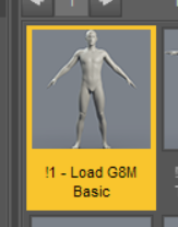
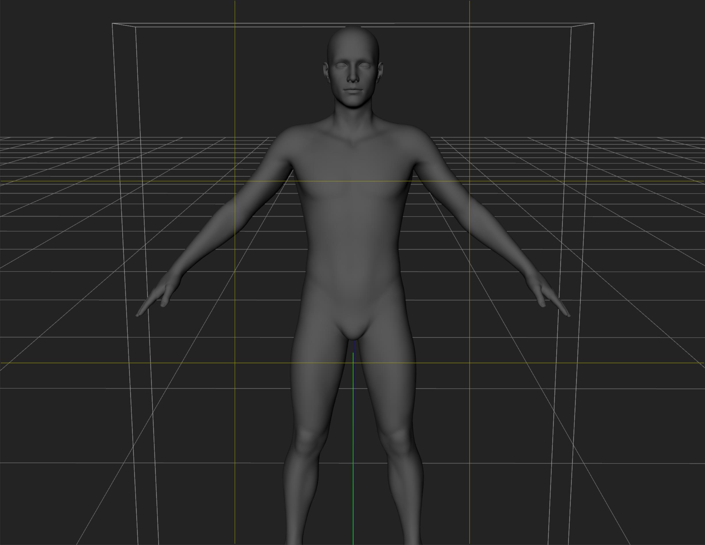
Before we can do anything, we need to load G8M into Studio. After clicking the "Load G8M Basic" command from the G8M Dev Kit you will see G8M load up into Studio. You'll immediately notice that the figure has no textures, and no eyelashes. This is exactly what we want:
Exporting the Base Object
This is all fine and dandy if you never want to pull the figure or object back into DAZ. But if you do, most likely things will fail spectacularly since the vertexes will be in the wrong place on the figure now.
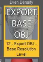
Fortunately, ITF's DevKit has a handy icon to export the Base OBJ for us automatically!
When you load this script a Save Dialog window will appear and the name will be pre-populated. Save this to some place that you can find later on, you're going to need this file that you just saved to import into Blender in the next step. :-)
And that's really it as far as Studio is concerned right now. The next few steps are going to be done in Blender so feel free to exit out of Studio to free up your system RAM if you need it!
Importing the Base OBJ into Blender
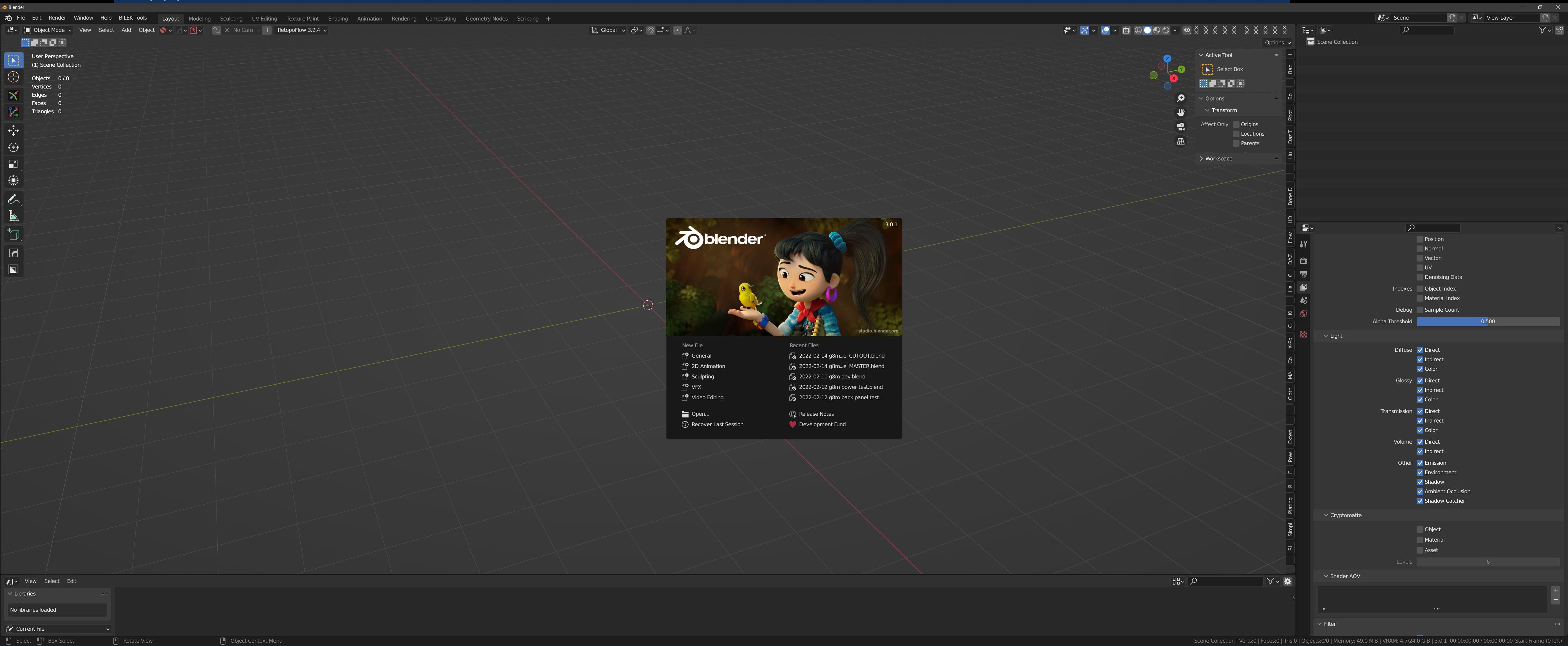
Go ahead and launch Blender. I am using Blender 3.0.1. (I always use the latest Blender version, but I do keep around the previous versions just in case!)
Now let's go and import that Base OBJ mesh of G8M that we saved out in the previous step.
Go to File � Import � Wavefront (.obj) �
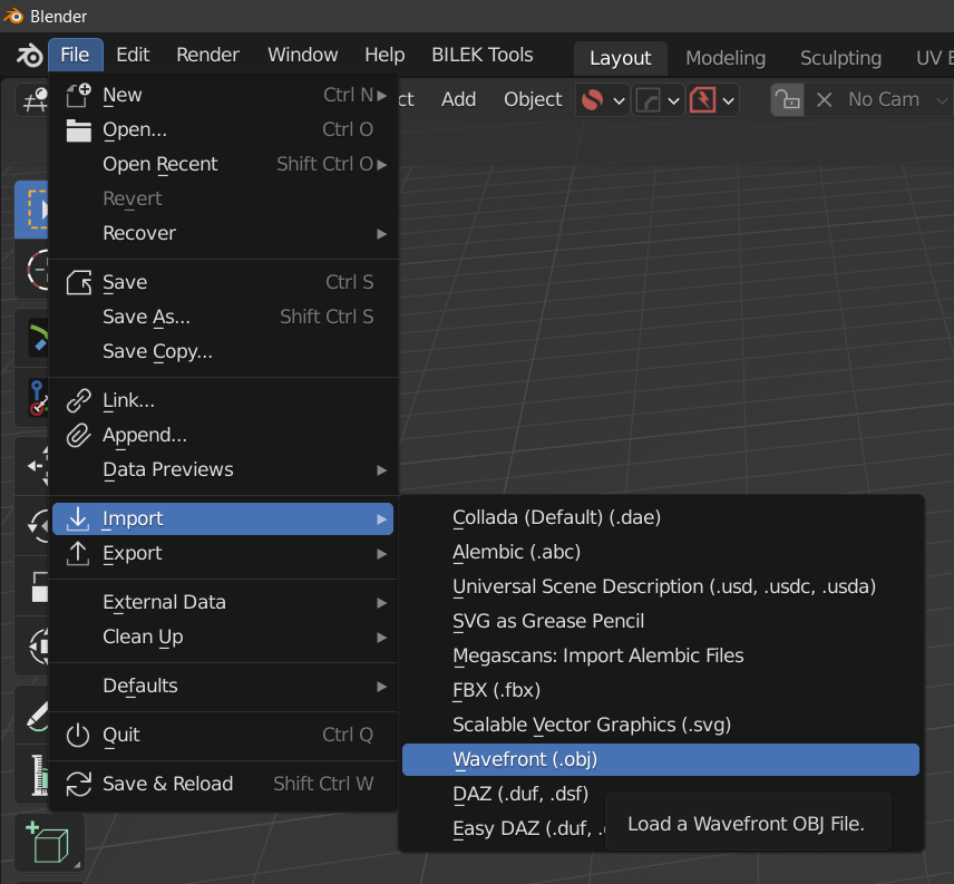
And select the object we saved out previously:
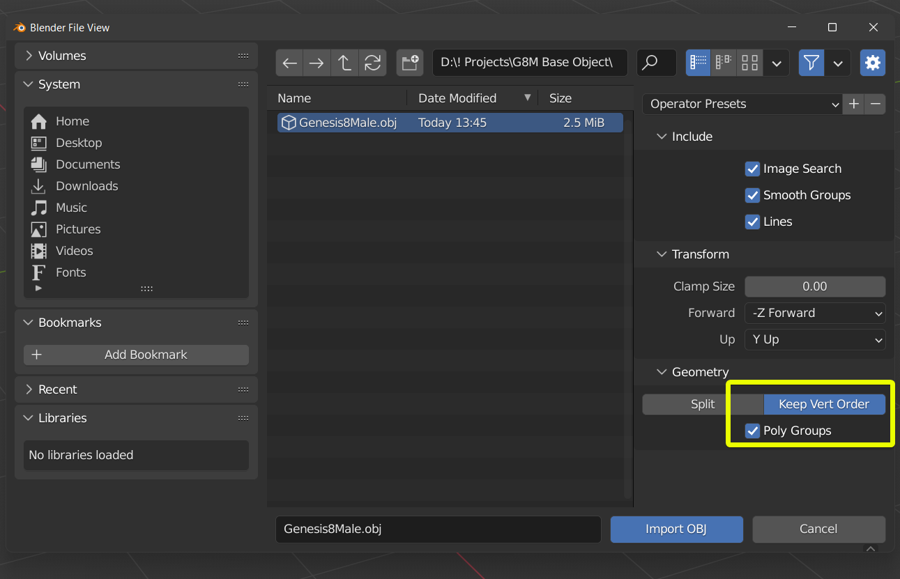
Only thing I make sure I do when importing objects from DAZ is I always make sure the Keep Vert Order is selected, and check the Poly Groups option. This is helpful to check later on and make sure you're not crossing poly groups which can cause problems.
Go ahead and click on Import OBJ. You should then see the object in your window. Or maybe not. Take a look at my screen:
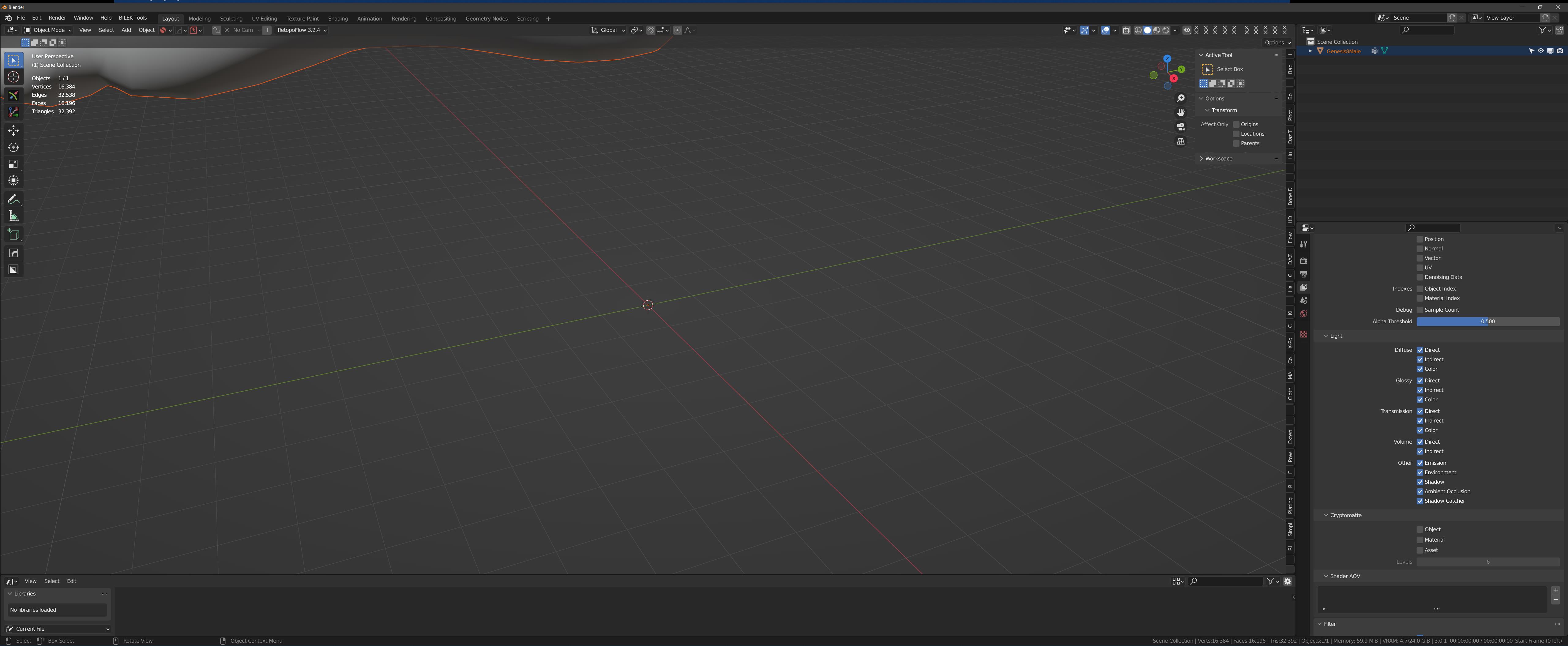
You can barely just see the right foot in the far upper-left of the screen. The reason for this is that DAZ's scale and Blender's scale are WAY off. Sure, we could change the scale but I've found it much easier to just work natively in DAZ's scale as you'll soon see.
You can use the scroll-wheel of your mouse to zoom-in or zoom-out. When you have the figure where you want it on your screen go ahead and move-on to the next page.
Selecting the edges
Now that the file is loaded we need to select the edges which are going to comprise our Geograft.
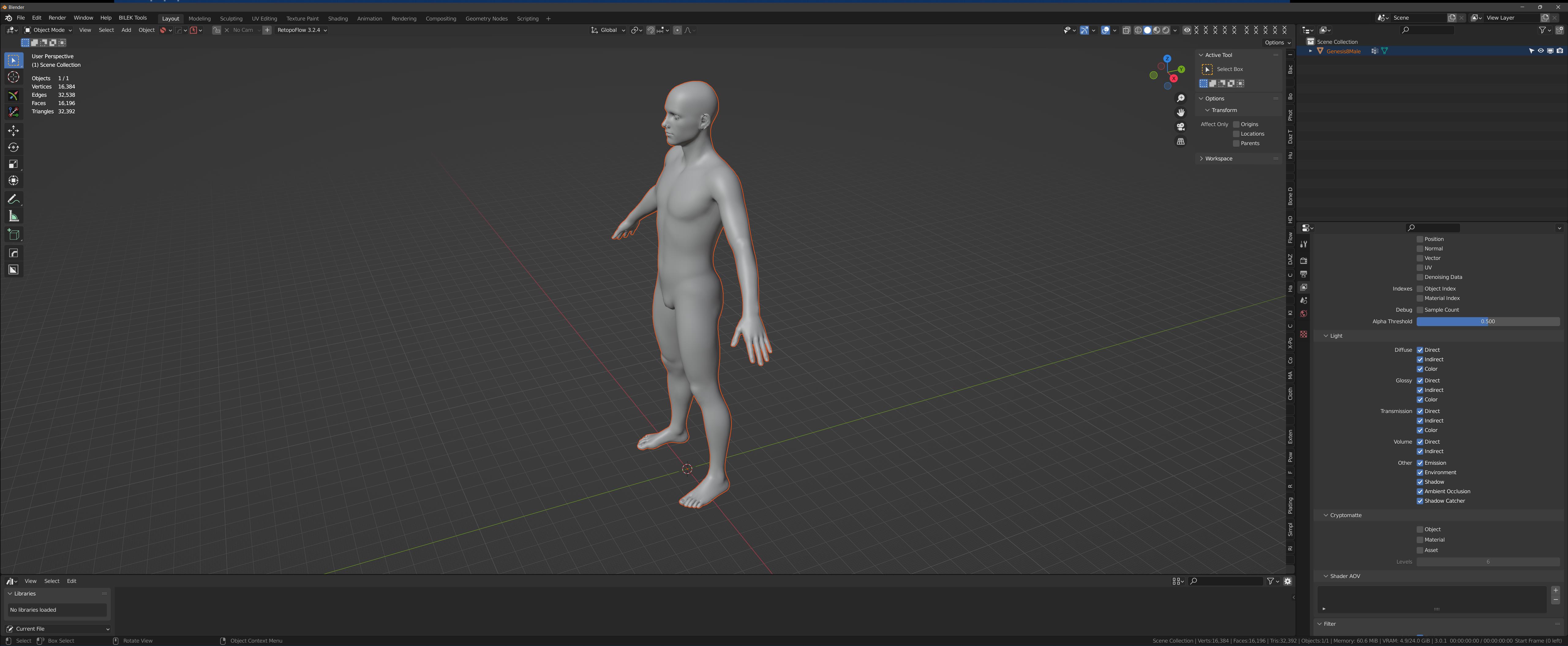
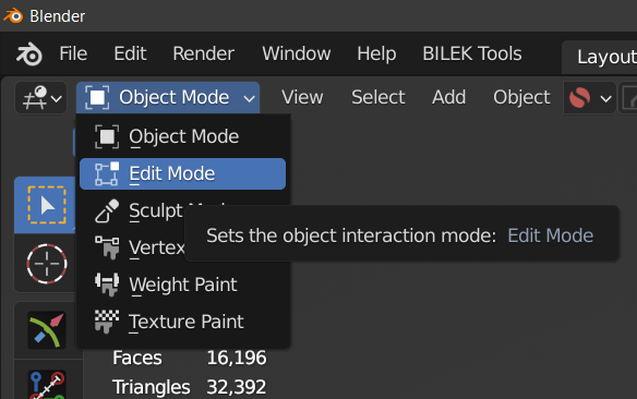
At this point, you are in Object mode in Blender. In this mode you can place, arrange, and even animate the objects in your scene; but you can't make any changes to their mesh/ geometry. For that, we need to be in Edit mode. First, click on your model once with your mouse button to the actual object is selected (its outline will turn from red to orange), then go ahead and click on the drop-down in the upper-left corner of the window and change it from Object Mode to Edit Mode:
When you go into Edit mode your screen may or may not look like this:
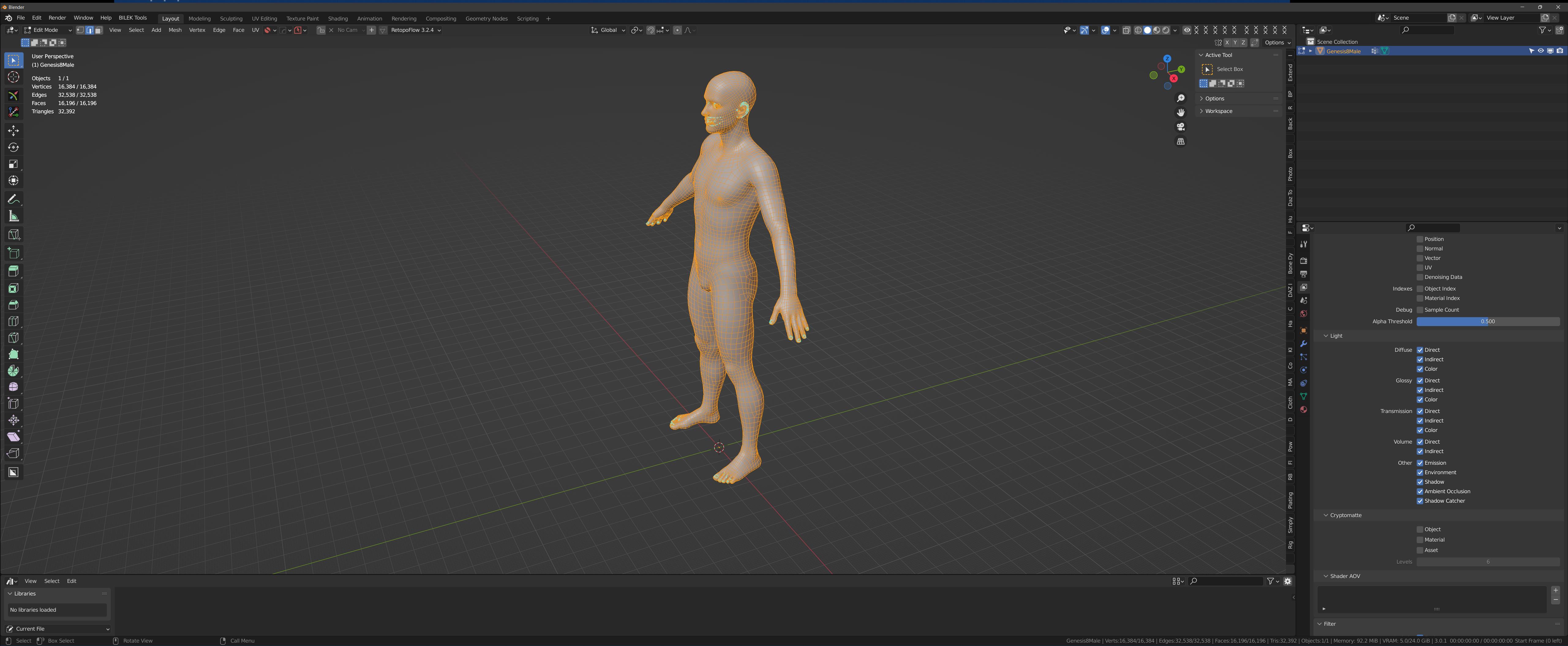
If it doesn't, don't worry. I'll show you. :-)
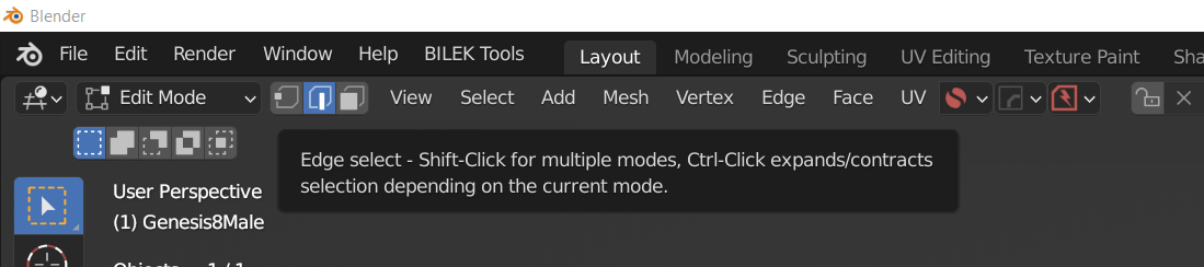
The first thing you want to do is set the selection mode to Edge as shown here:
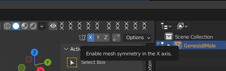
Next thing we want to do is set the X-axis symmetry. This will basically bisect your object and anything along the X-axis (in Blender this is the left-right from object mid-line) will be automatically selected for you along the opposite side. Naturally you only want this selected if you're doing something and you want an exact symmetrical selection. If you don't, then just leave this option off!
Now, you might still not see anything. No lines, no nothing! If you still don't see your figure look like this, read on!
The last thing we need to set is to enable the various overlays over our object! It's called the Show Overlays button, and it's at the very top of the scene window:
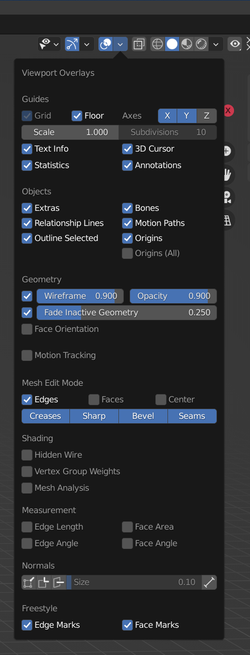
Make sure that button is turned on.
One final thing.
I assume you already know how to navigate Blender. If not, it's worth watching an introductory tutorial for that. But Blender 3 is pretty intuitive in its own right but some folks freak out when they accidentally turn off the gizmos and can't figure out how to get them back!
Well, fret no further. :-)
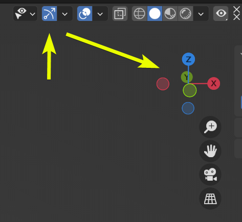
So if you accidentally disable the gizmo, now you know how to get it back!
Oy vey! Well, we're here to create a geograft, right? Well, we can't do that until we start to select some edges. For this example I'm going to create a power outlet for an android. But where to put it?
Well, if you look at any piece of machinery or equipment, whether it be your PC or even your microwave oven, the power cord (or power jack in this case) is always on the back, typically near the bottom, and that's right where we're going to put this geograft too.
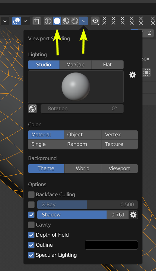
(I'm going to crank up the shadows in the Viewport Shading so the edge lines will have more contrast):
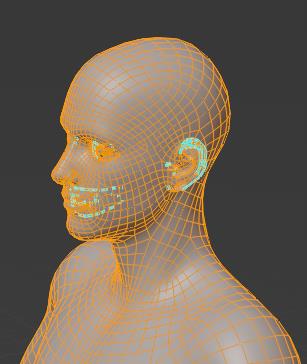
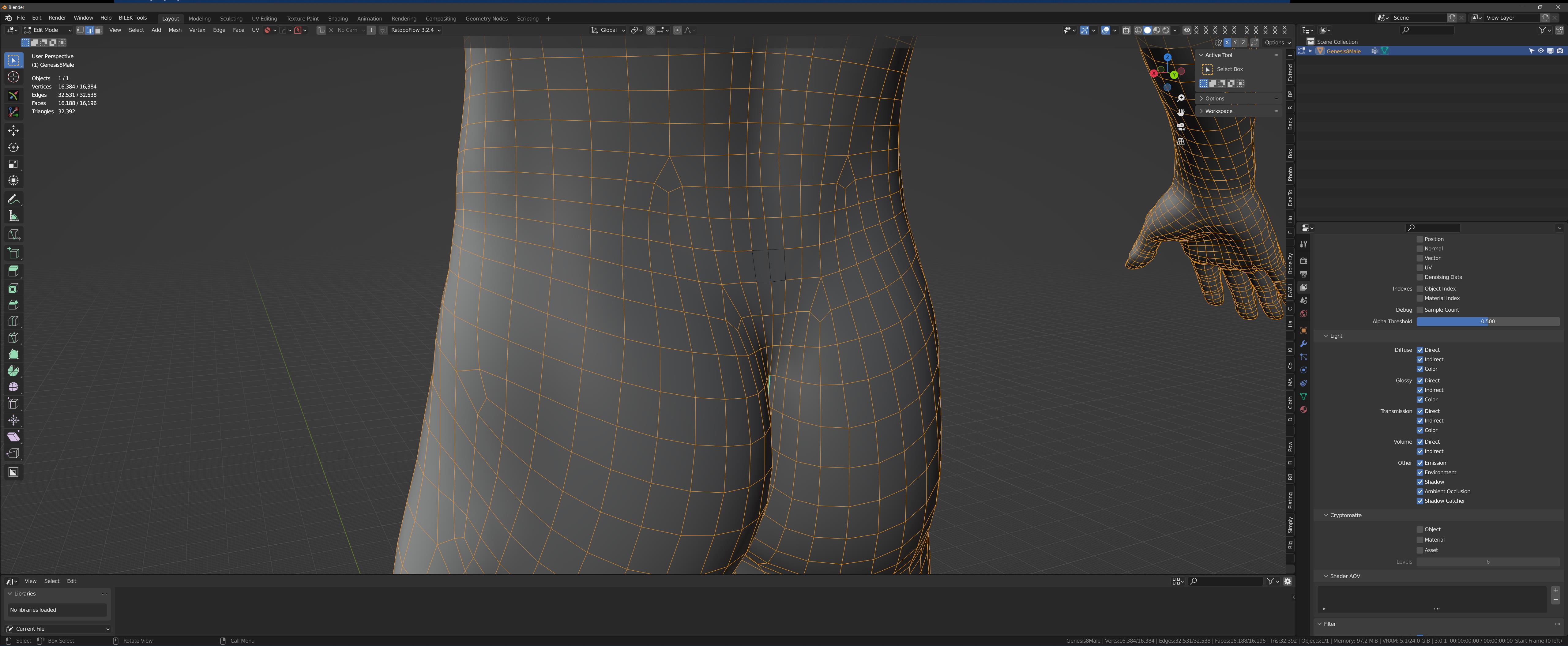
Now that I can see the faces better, I'm going to select some edges right in the sacral region of the lower-back of G8M:
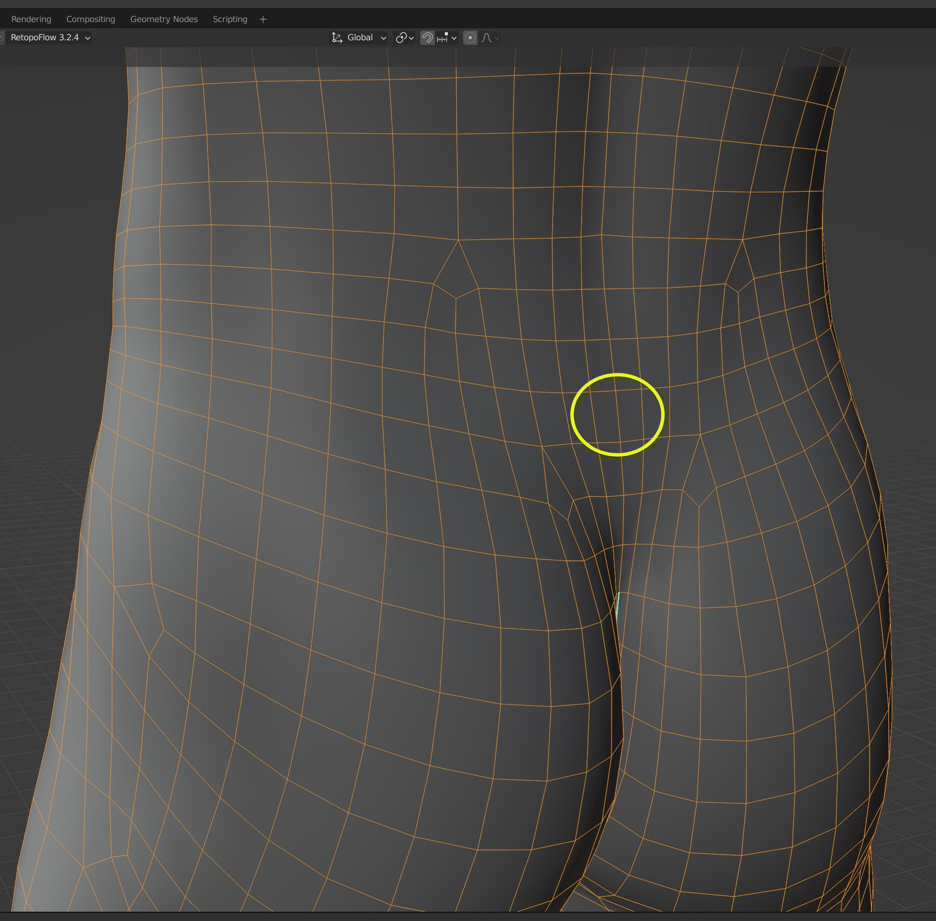
So just two (2) faces. Seven (7) edges. That's it. That's what we're going to use.
So use your mouse and hold down the shift-key and start selecting each edge, one by one. Be sure to get the one in the middle! Your selection should now look like this:
Now what we're going to do go to the Select menu and invert our selection so every other edge in our model is selected, except for the 7 edges we have selected right here:
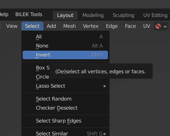
(Ignore the tool-top for the Invert selection, that appears to be a bug in Blender 3.0.1. LOL! Invert does not (de)select all vertices, edges, or faces. LOL)
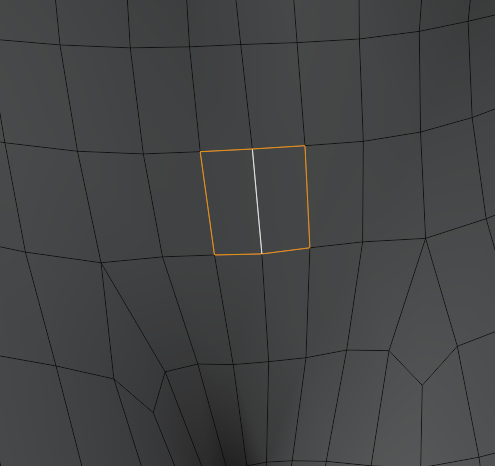
So now when you choose the Invert option, your figure will now look like this:
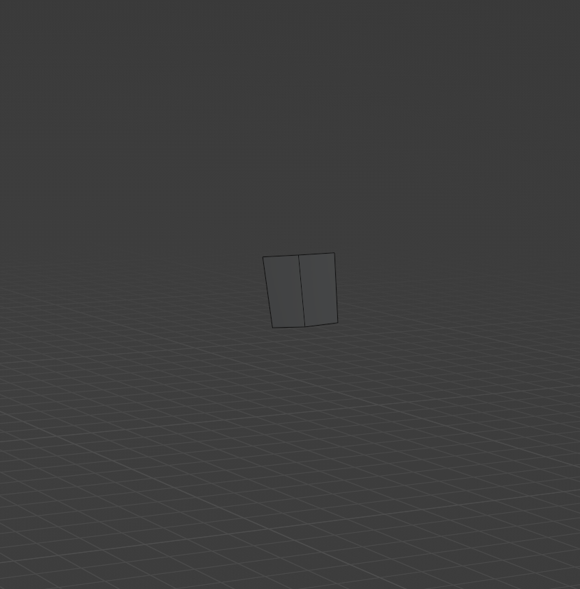
So as you can see, all of the edges are now selected with the exception of the seven edges we selected originally.
Now, let's delete every edge that is currently selected! Since we are working with our object's mesh, we'll use the Mesh menu to delete the edges:
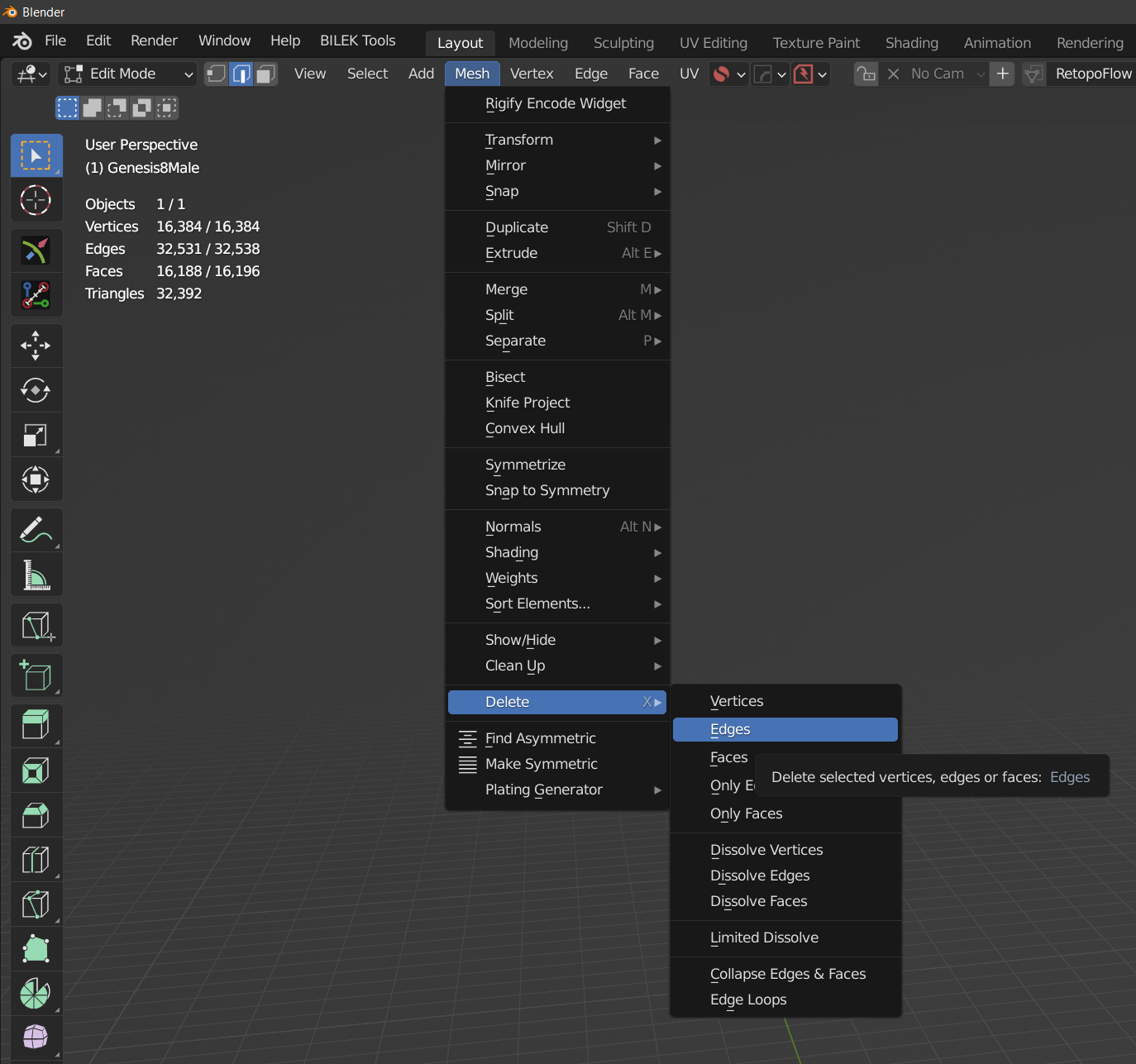
And when you're done, you should only now have (2) faces shown. (It may be difficult to see due to the grayness of everything but we'll fix that here in a second.)